
A cantilever from a rectangular cross-section is lying on an elastic Winkler foundation and loaded by distributed loading. The image shows the calculation of the maximum deflection and maximum bending moment.
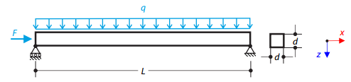
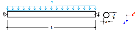
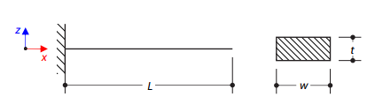
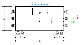
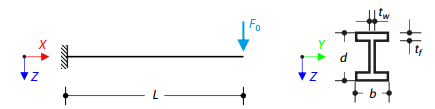
A steel beam with a square cross-section is loaded with an axial force and distributed loading. The image shows the calculation of the maximum bending deflection and critical load factor according to the second-order analysis.
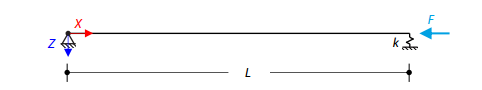
An axially loaded steel beam with a square cross-section is pinned at one end and spring-supported at the other. Two cases with different spring stiffnesses are considered. The verification example solves the calculation of the load factors of the beam in the image using the linear stability analysis.
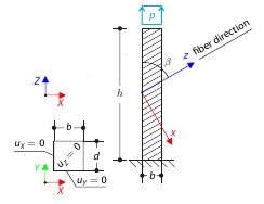
A cantilever with fibers that do not run in direction of the beam axis from a square cross‑section with tensile pressure. Calculate the maximum deflection.
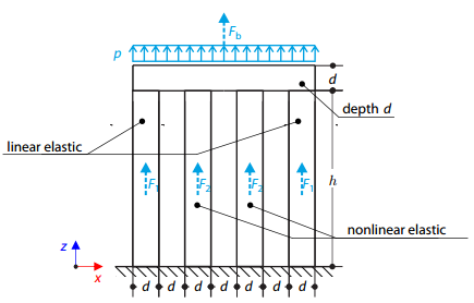
Four columns are fixed at the bottom and connected by a rigid block at the top. The block is loaded by pressure and modeled by an elastic material with a high modulus of elasticity. The outer columns are modeled by linear elastic material and the inner columns by a stress-strain diagram with decaying dependence. Assuming only the small deformation theory and neglecting the structure's self-weight, determine its maximum deflection.
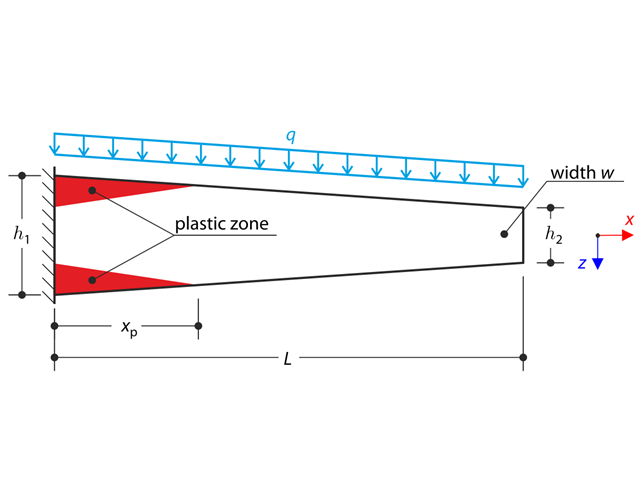
A tapered cantilever is fully fixed on the left end and loaded by a continuous load. Plastic material is considered for the calculation.
A steel cable or membrane with pins on both ends is loaded by distributed loading. Neglecting its self-weight, determine the maximum deflection of the structure using the large deformation analysis.
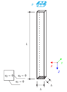
A vertical cantilever with a square cross-section is loaded at the top by tensile pressure. The cantilever consists of an isotropic material. Calculate the deflection.
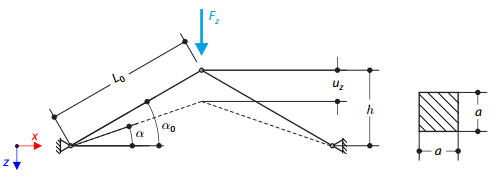
A structure is made of two trusses, which are embedded into the hinge supports. The structure is loaded by concentrated force. The self-weight is neglected. Determine the relationship between the loading force and the deflection, considering large deformations.
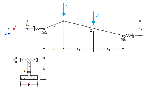
A structure made of I-profile trusses is supported on both ends by spring sliding supports and loaded by transversal forces. The self-weight is neglected in this example. Determine the deflection of the structure, the bending moment, the normal force in the given test points, and the horizontal deflection of the spring supports.
A steel cantilever with a rectangular cross‑section is fully fixed on one side and free on the other. The aim of this verification example is to determine the natural frequencies of the structure.
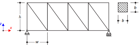
A planar truss structure is simply supported. The aim of this verification example is to determine the natural frequencies of the structure.
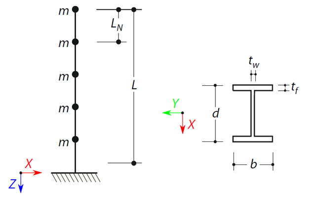
A cantilever beam with an I-beam cross-section of length L is defined. The beam has five mass points with masses m acting in the X-direction. The self-weight is neglected. The frequencies, mode shapes, and equivalent loads of this 5-DOF system are analytically calculated and compared with the results from RSTAB and RFEM.
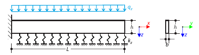
A cantilever from a rectangular cross-section is lying on an elastic Pasternak foundation and loaded by distributed loading. The image shows the calculation of the maximum deflection and maximum bending moment.
A masonry wall is exposed to a distributed load in the middle of its upper section. The Isotropic Masonry 2D material model is compared with the Isotropic Linear Elastic model, with surface stiffness property Without Tension in the nonlinear calculation.
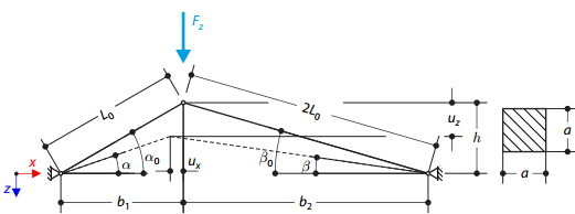
A structure is made of two trusses of unequal length, which are embedded into the hinge supports. The structure is loaded by concentrated force. The self-weight is neglected. Determine the relationship between the loading force and the deflection, considering large deformations.
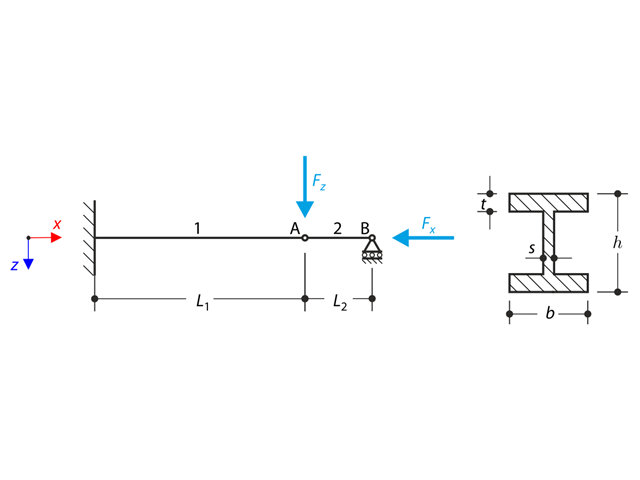
A structure made of an I-profile is fully fixed on the left end and embedded into the sliding support on the right end. The structure consists of two segments. The self-weight is neglected in this example. Determine the maximum deflection of the structure, the bending moment on the fixed end, the rotation of segment 2, and the reaction force at point B by means of the geometrically linear analysis and the second-order analysis. The verification example is based on the example introduced by Gensichen and Lumpe.
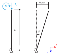
Consider a rigid scaffolding tube, fixed at the bottom using the Scaffolding Nodal Support and loaded by both a moment and a force. Calculate the maximum deflection with consideration of initial slippage.
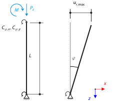
Consider a rigid scaffolding tube, fixed at the bottom using the Scaffolding Nodal Support and loaded by both a moment and a force. Calculate the maximum radial deflection by exceeding the capacity of the scaffolding support.
Time history analysis of a cantilever beam (SDOF system) excited by a periodic function. Vertical deformations and accelerations calculated with direct integration and modal analysis in RF‑/DYNAM Pro - Forced Vibrations are compared with the analytical solution.